MIL-PRF-38135C(USAF)
3.5.8 Static pressure. The pointer shall not change position due to internal leakage more than
1 knot when a pressure sufficient to cause full-scale deflection is applied.
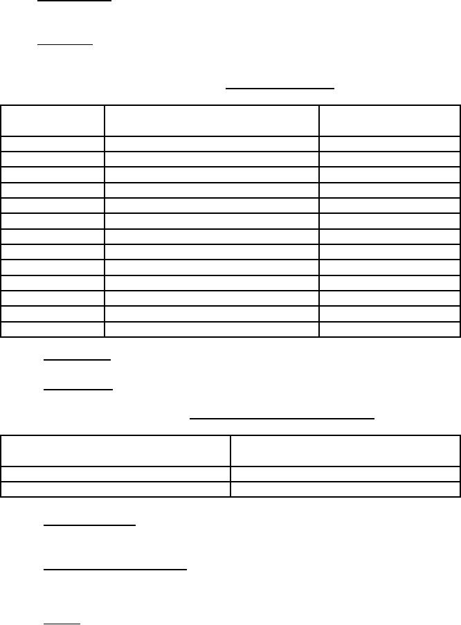
3.5.9 Scale error. The scale error (see 6.3.1) of the indicator shall be within the tolerances
specified in table II.
TABLE II. Scale error tolerances
Test point
Differential pressure
Tolerance
(±knots)
(inches Hg)
0
0
10
60
0.172
3
80
0.308
3
100
0.482
3
120
0.696
3
150
1.092
3
200
1.962
5
300
4.541
10
400
8.397
15
500
13.797
20
600
21.109
20
700
30.816
20
800
43.009
20
3.5.10 Friction error. The friction error shall be within the tolerances in table II.
3.5.11 Position error. The position error shall be within the tolerances in table III.
TABLE III. Friction and position error tolerances
Indicated airspeed
Tolerance
(±knots)
(knots)
60 to 200
3
201 to 850
10
3.5.12 Dielectric strength. The indicator shall withstand application of 500Vac between the pins
and case for 5 seconds without insulation breakdown.
3.5.13 Dial and cover glass location. The distance between the front surface of the bezel and the
outside of the cover glass shall be 0.062 inch or less. The distance between the inside surface of
the cover glass and the dial shall 0.125 inch or less.
3.5.14 Pointer. There shall be no oscillation in excess of ±5 knots of the pointer while the
indicator is vibrated. The pointer shall be adjustable. The pointer shall conform to MS33585-8
and shall be finished in lusterless white, color number 37875 of FED-STD-595.
5
For Parts Inquires call Parts Hangar, Inc (727) 493-0744
© Copyright 2015 Integrated Publishing, Inc.
A Service Disabled Veteran Owned Small Business